| Scirocco Engine Swap - Knock Sensor Installation | |||||||||||||||||||||||||||||||||||||||||||||||||
| Installation of a high
compression engine (such as 3A or ABA) into a vehicle that does not have a knock sensor
requires the installation of a knock sensor. The knock sensor protects the engine
from destructive engine knock by retarding the timing upon detection of knock, and also
controls timing advance. Aftermarket options are available, but the most affordable
option is to retrofit a factory knock sensor with wiring harness. The factory VW knock sensor can be found in any CIS-E equipped VW such as the 1985 to 1988 GTI and GLI, and 1986 to 1989 16V. Wire colors/pins may differ depending on the donor vehicle and the vehicle in which the knock sensor is being installed. Wiring diagrams should be obtained for both vehicles to assure proper installation. You MUST use a distributor from a vehicle originally equipped with a knock sensor. This installation is specifically a 1985 Scirocco with 3A/JH 2.0L 8V engine, utilizing the knock sensor from a 1987 GTI. |
)
|
||||||||||||||||||||||||||||||||||||||||||||||||
| Wiring Preparation | |||||||||||||||||||||||||||||||||||||||||||||||||
| Wiring diagrams
should be obtained for the donor vehicle and the vehicle in which the knock sensor is
being installed. The Bentley service manuals are an excellent source for this information.
Be aware, though, that the wiring may differ slightly from the published diagrams.
Be flexible and ready for possible differences. The following diagrams/links may be of use, but are not guaranteed for accuracy. 1986 Wiring Diagram (.pdf
file) |
|||||||||||||||||||||||||||||||||||||||||||||||||
Wiring harness
preparation is fairly simple once you determine which wires are needed.
|
|||||||||||||||||||||||||||||||||||||||||||||||||
| Click the diagram to the right. This will open a new window, with the diagram and chart above. Print it out for your reference. | 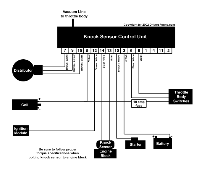 |
||||||||||||||||||||||||||||||||||||||||||||||||
| This mess of wires was pulled from the donor vehicle. Only a small portion will be used, but pulling everything from the donor vehicles insures all wiring and connectors will be available. | ) |
||||||||||||||||||||||||||||||||||||||||||||||||
| This shows all the wiring, knock sensor, and knock sensor box. | ) |
||||||||||||||||||||||||||||||||||||||||||||||||
| This is the main harness that attaches to the knock sensor box. Factory connector was left attached (bottom left). | ) |
||||||||||||||||||||||||||||||||||||||||||||||||
| This part of the harness contains the wiring for the knock sensor, the wires that attached to the distributor, and the wire for power "50". The wiring harness was modified so the power "50" wire would use the factory connector. | ) |
||||||||||||||||||||||||||||||||||||||||||||||||
| This part of the harness goes to the throttle body switches. The yellow wire is fused and connected directly to power "15". | ) |
||||||||||||||||||||||||||||||||||||||||||||||||
| This is a Type 2 knock sensor.
Specific torque values must be used during installation to insure proper operation. Type 1: 7-9 ft. lbs. |
) |
||||||||||||||||||||||||||||||||||||||||||||||||
| Installation | |||||||||||||||||||||||||||||||||||||||||||||||||
| The wiring can be run through
existing grommets to avoid drilling any holes. If you use factory connectors, they
can be disassembled and reassembled after pulling the wires through. Disassembling the connector is as simple using a paper clip and pushing through the "wire prong" side. |
) |
||||||||||||||||||||||||||||||||||||||||||||||||
| Pin #12 (Green/White) Carefully cut a small opening in the harness cover about 6" from the ignition module connector to access the green/white wire. Cut the wire and pull it out, then tape the opening. This gives you room to work when soldering the wires. You will connect to the wire coming from the ignition module. |
) |
||||||||||||||||||||||||||||||||||||||||||||||||
| Pin #5 (Yellow) and
power for throttle switches Power "15" can be sourced at the coil (black wire on back side). |
) |
||||||||||||||||||||||||||||||||||||||||||||||||
| Pin #10 (Brown/Yellow) Power "50" can be sourced at the starter. A "piggyback" connector from Radio Shack made installation simple. |
) |
||||||||||||||||||||||||||||||||||||||||||||||||
| You will need to use the factory
full throttle and idle switches from the knock sensor donor vehicle. If you did a 3A
swap, these switches are on the 3A throttlebody. This picture shows the full-throttle switch and wire connector on the Audi 3A throttlebody. |
) |
||||||||||||||||||||||||||||||||||||||||||||||||
| This picture shows the idle switch on the Audi 3A throttlebody. | ) |
||||||||||||||||||||||||||||||||||||||||||||||||
| The full-throttle and idle switches were mounted to the existing throttlebody. (which in this case, was the larger A2 throttlebody). | ) |
||||||||||||||||||||||||||||||||||||||||||||||||
| If your car was originally equipped with a full-throttle switch, you will need to "piggyback" it with the full-throttle switch for the knock sensor. This is easily accomplished by using longer switch mounting screws. |
) |
||||||||||||||||||||||||||||||||||||||||||||||||
| A vacuum line needs to be run to the knock sensor box. A "T" connector was installed near the throttlebody in the line that went to the original distributor with vacuum advance. | ) |
||||||||||||||||||||||||||||||||||||||||||||||||
| Bolt the knock sensor to the block. Be sure to observe proper torque specifications. | ) |
||||||||||||||||||||||||||||||||||||||||||||||||
| Connect the wires to the distributor. | ) |
||||||||||||||||||||||||||||||||||||||||||||||||
| Connect PIN#3 (brown wire) to a ground. The battery is always a safe bet for grounding. |
|||||||||||||||||||||||||||||||||||||||||||||||||
| Double check your
installation and try starting the car. If the car cranks but does not start, the
distributor timing may need advanced. |
|||||||||||||||||||||||||||||||||||||||||||||||||
| Miscellaneous Observations | |||||||||||||||||||||||||||||||||||||||||||||||||
| The car started fine
before adding the knock sensor. The distributor had not been changed. The car
would not start. Timing had to be advanced Prior
to KS installation, the car was difficult to start when warm. I blamed this solely
on an old starter and higher compression. The problem disappeared after installing
the knock sensor. |
|||||||||||||||||||||||||||||||||||||||||||||||||
| Cost Overview | |||||||||||||||||||||||||||||||||||||||||||||||||
| The price of the knock
sensor box and wiring harness will vary depending on your source. A knock sensor costs around $50.00 - get a new one! Miscellaneous wire connectors and heat shrink should be
$10.00 to $15.00. |
|||||||||||||||||||||||||||||||||||||||||||||||||
| Summary | |||||||||||||||||||||||||||||||||||||||||||||||||
| Wow! A world of difference... lots of new found power! | |||||||||||||||||||||||||||||||||||||||||||||||||
)